Next: Applications Up: Longitudinal electrodynamic forces Previous: Theoretical discussion
![]()
![]()
![]()
![]()
Next: Applications
Up: Longitudinal
electrodynamic forces Previous: Theoretical
discussion
In this chapter we will apply the Maxwell stress approach to some of the experiments, and compare the theoretical and experimental data.
Let us begin with analysing the multi-arc generator. Segments of a copper rod are stacked vertically. A spring with a light pressure keeps them in contact. When a current pulse is passed the pieces separate.
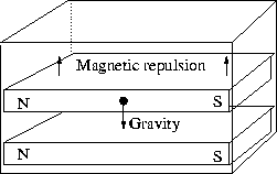
A longitudinal repulsion acts between neighbouring segments, causing them to repel each other. This repulsion is balanced by gravity and the light spring pressure. The downward force is of course greatest on the bottom piece, as it has to carry the gravity of all the other pieces. In order to separate the bottom piece from its upper neighbour all the segments above it have to be levitated by its repulsion. The situation is similar to magnets stacked side by side in a box, Figure 4.1.

Figure 4.1: Magnets stacked in a box. The upper magnet levitates
due to the magnetic repulsion.
Is the Maxwell stress strong enough to separate the pieces? Let us consider the bottom piece and calculate the required forces:

The forces that the Maxwell stress has to overcome are in the range 0.08-3.0N, plus the additional light spring pressure. In the cases where aluminium and copper segments were mixed, the force should be somewhere in between. The force from the Maxwell stress is:
![]()
With i = 6-25kA we have ![]() N, well enough to separate all the segments. The excess part of the
force
compresses the spring until the forces balance. The above reasoning
suggests
that if a weak current is used, only segments higher up will separate.
N, well enough to separate all the segments. The excess part of the
force
compresses the spring until the forces balance. The above reasoning
suggests
that if a weak current is used, only segments higher up will separate.
Let us now study Nasi ![]() owski's experiment. Could the Maxwell stress be responsible for the
wire
breaks? As we have seen in the theoretical discussion, the wire should
be subjected to a radial pinch pressure and an axial stress. In the MIT
experiments Graneau used 1.2mm Al wires, and currents in the range
5-7kA.
The wires shattered at about 6kA. The maximum of the longitudinal
Maxwell
stress would be:
owski's experiment. Could the Maxwell stress be responsible for the
wire
breaks? As we have seen in the theoretical discussion, the wire should
be subjected to a radial pinch pressure and an axial stress. In the MIT
experiments Graneau used 1.2mm Al wires, and currents in the range
5-7kA.
The wires shattered at about 6kA. The maximum of the longitudinal
Maxwell
stress would be:
![]()
Here r is the radial distance from the center or the
conductor,
and R the radius of the conductor. In addition to this a pinch
pressure
of the same magnitude acts. As the stress profile in the wire is quite
complicated, we could expect the maximum stress across any surface to
be
of same the order as the sum, i.e ![]() . This is not a great stress. However, the wire was severely weakened
by
being heated to almost its melting point before it broke. Aluminium at
room temperature has a tensile strength of about
. This is not a great stress. However, the wire was severely weakened
by
being heated to almost its melting point before it broke. Aluminium at
room temperature has a tensile strength of about ![]() . At 600°C it is reduced to roughly
. At 600°C it is reduced to roughly ![]() [2].
Of course there is still a gap to
[2].
Of course there is still a gap to ![]() . It may be that the temperature was substantially higher in some part
of the conductor. The shock of the stress, as it was applied quite
rapidly,
in about 1ms, may have contributed to shatter the wires. Nasi
. It may be that the temperature was substantially higher in some part
of the conductor. The shock of the stress, as it was applied quite
rapidly,
in about 1ms, may have contributed to shatter the wires. Nasi ![]() owski used weaker currents than Graneau. His wires also showed more
signs
of melting at the surface, a fact that supports the above arguments.
(Nasi
owski used weaker currents than Graneau. His wires also showed more
signs
of melting at the surface, a fact that supports the above arguments.
(Nasi
![]() owski's
copper wires were sometimes heated to 900-1000°C -- almost
to the melting point.)
owski's
copper wires were sometimes heated to 900-1000°C -- almost
to the melting point.)
In order to make more clear conclusions, more accurate data on wire temperatures and tensile strength is needed.
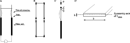
Let us now examine the railgun deformation. The rails deformed, as if subjected to compressive forces, Figure 4.2A.

Figure 4.2: (A) Compressive forces in the railgun. (B)
Separation
forces at the ends in the impulse pendulum. (C) Euler breaking. (D)
Section
of the rail extensions.
The situation is more clear cut in the impulse pendulum experiment, as no influences from the corners can be expected in that case, Figure 4.2B. However, from the Maxwell stress approach, we expect the compressive forces in the two cases to behave similarly.
How great a force would be needed to deform the thin rails in Graneau's experiment? Obviously we have a situation with Euler breaking. As one end is free to move, but supported from one side, we have Euler's second case, Figure 4.2C. The force is given by:
![]()
The notation is quite confusing. E here means the Young
modulus;
![]() the
least area momentum of inertia; L is the length of the rod (or
rail in this case); and
the
least area momentum of inertia; L is the length of the rod (or
rail in this case); and ![]() is a geometric factor depending on how the rod is fixed. The least area
moment of inertia, see Figure 4.2D,
is:
is a geometric factor depending on how the rod is fixed. The least area
moment of inertia, see Figure 4.2D,
is:
![]()
The width (b) is 12.7mm and the thickness (h) of the
rail
extensions is said to be much smaller than that of the thicker 1.3mm
(0.5'')
rails [21].
Let us assume that h was at least 0.5mm. With ![]() , L=300mm,
, L=300mm, ![]() and E=70 and
and E=70 and ![]() for aluminium and iron, respectively, we have:
for aluminium and iron, respectively, we have:
![]() (Aluminium) and
(Aluminium) and ![]() (Iron).
(Iron).
How does this compare with the Maxwell stress? The force would be:
![]()
where I now means the current in the circuit and ![]() is the magnetic permeability of vacuum. Graneau reports he used
currents
in the range 10-100kA [21],
which gives
is the magnetic permeability of vacuum. Graneau reports he used
currents
in the range 10-100kA [21],
which gives
![]()
well enough to cause severe deformation of the rails.
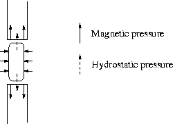
Perhaps we should also consider the impulse pendulum situation to elucidate how longitudinal forces and pinch forces act. As the ends are in front of each other, without corners in the neighbourhood, the situation is more straightforward to visualize, see Figure 4.3.

Figure 4.3: The forces at the interface between the rods.
At the end of the rods a longitudinal Maxwell stress acts. This tends to separate the rods, the force being strongest at the periphery, and zero at the center.
In addition to this a pinch pressure acts hydrodynamically. As the rods separate a small distance, an arc strikes between the ends. The pinch pressure in this arc causes it to contract radially, and thus stretch in the middle, transferring radial pressure into axial. This hydrodynamical pressure also acts on the ends of the rods, mechanically. This pressure is of course greatest at the center of the rod.
Thus the force on each end is a sum of the longitudinal Maxwell stress, and the hydrodynamical arc pressure. If we regard the two rods in contact as one single rod, it is clear that it should `break' at the interface, as its tensile strength is weakest there.
An interesting question is if the longitudinal Maxwell stress is perfectly balanced all along a conductor, or if it could contribute to the forces between two parts of a circuit.

Figure 4.4: End force balanced by force in the corner.
Let us consider the impulse pendulum, Figure 4.4. Can we, for example, be sure the the Maxwell stress from the end faces of a pi-frame is perfectly balanced by the Maxwell stress in the corners, where the conductor is no longer straight? Or to put it more clear cut: When it comes to forces between two parts of the same circuit, does the Grassmann and the Ampère force laws differ quantitatively? In the impulse pendulum case, which can be regarded as generic, very precise calculations have been performed by Moyssides [50]. The predicted forces seem to be equal, the small differences being due to the numerical integration.
Where we have an asymmetry, a change in diameter, or a bend, we
necessarily
have a current that moves transversely with regard to the current in
its
neighbourhood, and consequently Lorentz forces. It is thus the
asymmetry
in the Lorentz forces that cause the movements, as long as the circuit
doesn't deform itself axially. Typical asymmetry movements are Hering's
crooked wire experiment and the copper submarine. Typical axial
deformations
are railgun bucking, the Multiarc generator (at least far from the
ends),
and Nasi ![]() owski's wire fragmentation.
owski's wire fragmentation.
Many of the asymmetry movements can be visualized as stretching of the magnetic flux (which in those cases is equivalent to considering the Lorentz forces). This was Hering's approach. If the current is uniform all the repulsions balance. Movements manifest whenever the flux density is weaker at some part of the conductor.

Figure 4.5: Nonuniform magnetic flux causing the separation of
the
bars.
Consider e.g. the separating bars,Figure 4.5. As the current diverges outside the faces of the rods, the flux density is weaker there. The more concentrated flux at the middle overpowers the weak flux at the ends, causing the two bars to separate. Similar arguments can be applied to the chain, the copper submarine, and Hering's wire movement.